The boards need a LMR logo
The boards need a LMR logo easy to do on the copper. Is someone working on that?
The boards need a LMR logo
The boards need a LMR logo easy to do on the copper. Is someone working on that?
You mean the silkscreen?
You mean the silkscreen?
An image we can import into
An image we can import into the board itself, black and white so we can etch it into the pcb.
That’s what I’m talking
That’s what I’m talking about. A black/white image that can be imported on the copper or silk screen. Like SparkFun’s flame logo.
I tried to make that logo
I tried to make that logo (from “about”-page, top menu, you can find all logo in vector) - but our logobot is just not cut for small print IMO. Someone shoudl have thought of that 
However, though logo’s look good, I think the link to the page where the board is discussed / comes from will be of much greater use. And that goes well in small resolutions.
**We can always throw a LMR **
We can always throw a LMR on the board
Great idea
Yes, the logobot does not make for a good silkscreen but it might work. The bigger the better of course. This is a standard 50% threshold bitmap @ 200x200 pixel res. version of the bot (1" square):

this one is 1/2" square

The 1/2" looks real small in EAGLE, but hey, something is better than nothing!
This will work great!
This will work great!
Very nice. If you want to
Very nice. If you want to use the EAGLE import or something else that needs .bmp or whatever let me know, I can get them for you.
Eagle 5.11 has import-bmp,
Eagle 5.11 has import-bmp, The 2nd revision of the SN754410 board now has a LMR logo and pull up resistors.
Nice! I want to see that!
Nice! I want to see that!
Then I´m in (as a potential
Then I´m in (as a potential buyer)!
My vote would be for …
ALABTU
Heres the second revision of
Heres the second revision of the SN754410 1A motor driver:
Note The Little LMR bot and the backwards lettering, all to be fixed in 2.1.
With revision 2 comes pulldown resistors (optional when you assemble the board) and the board is optimized for multiple boards. This means you can stack multiple SN754410 boards together! Simply assemble them as usual but use wire wrap headers instead, and it allows stacking of the control lines. All it then needs is a wire jumper for reach motor terminal. This board (revision 2.1 will fix backwards lettering) Will sell for 15 dollars assembled, excluding shipping.
Worked on a lipo charger
Worked on a lipo charger with usb and external input(solar) connectors. 3.3v Reg onboard supplied by battery or external power(usb through charging unit). Will work on the layout today. First smt project…so we’ll see how it goes. Similar to the SF setup(uses the mcp) only the vreg chip is set to specific voltage looking to set it up to fit in some small cases that I have. Not sure how useful they will be to others as they are ment for low power systems, with specific focus on it being used with an msp430 chip. Still, someone might find it useful as well. :)
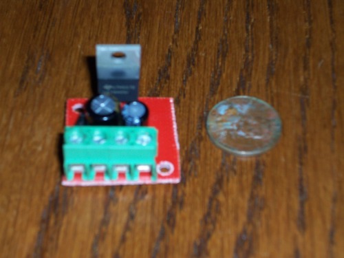
** Voltage regulator board,**
Voltage regulator board, compatable with 78xx regulators. 5$ per board, made out of red PCB material and exactly 1 square inch :)
I’d rather see a LDO voltage
I’d rather see a LDO voltage regulator on the board than the 78xx series.
Some dude named Krumlink asks about some alternatives in this post on http://www.electro-tech-online.com/datasheets-manuals-parts/32193-ldo-replacement-7805-a.html.
4 Years ago, things
4 Years ago, things change…
Anyways a L2940 is a LDO that is compatable with the 7805, Will work the same, compatable too, just use a tantalum capacitor instead of a monolithic disc capacitor.
You can solder different
You can solder different values of capacitors into the board to meet the requirements of the LM2940, a .47UF capacitor on the input and a 22UF capacitor on the output. Also, I would replace the diode (in the board) with a jumper to avoid the 1.4V drop, to ensure you can run the regulator at 5.something volts.