I'm tryng to make a herbie circuit but can't get it to work. I attached a link of my EXACT circuit on a breadboard. Can someone tell me what I am wiring wrong?
I don’t know if it’s a mistake in the drawing or the circuit, but here goes:
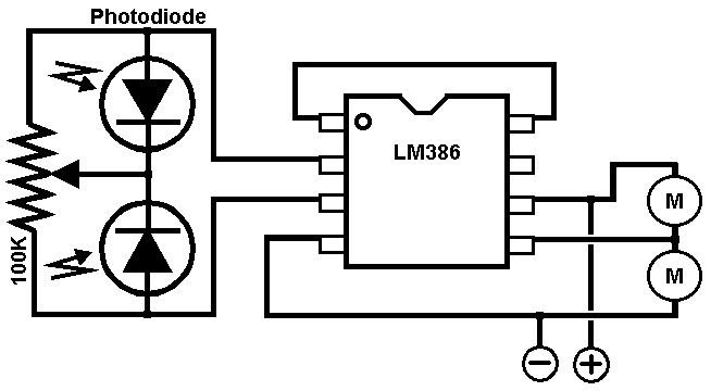
1. Your resistor seems like it’s a fixed resistor and not a trim pot. Use a trimpot. Also, it’s not connected to anything.
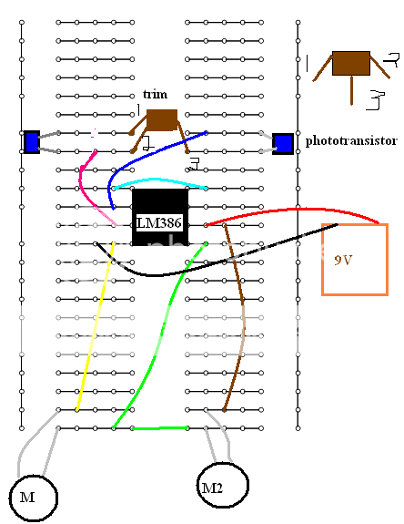
2. Your phototransistors are parallel. They are not in the schematics. The same seems to go for the motors. I have edited in your picture here. It’s just some cut’n’paste, but try to follow the wires and compare them with your drawing and the schemtaics. Remember that the horizontal lines in the drawings are wires too. I have added the schematic symbols for the photo diodes, so you can see, which way the are to be mounted (it won’t work if they are mounted backwards)
Thank you guys so much for helping me! Especially, with redrawing my entire circuit. As you guys can tell I’m new to the world of robotics. So I’m slowly learning things haha.
I rewired my circuit to match yours. Unforuntatly, I thought a 100k resistor could work as a 100k trimpot (yeah, I was wrong haha). So I plan on going out to get one today. I was hoping you could tell me what exactly is a trimpot/potetiometer?
also, which of these would work for my ciruit? I put links below. Thanks again guys!
Sorry to trouble you again but I’m having some more trouble. I copied the drawing and rewired everything but for some reason it still wont work. Only the left motor is running and it doesn’t seem to be sensitive to light. I am actually using phototransistors instead of photodiodes but I read that they’re the same (unless I was told wrong haha).
<o:p></o:p>
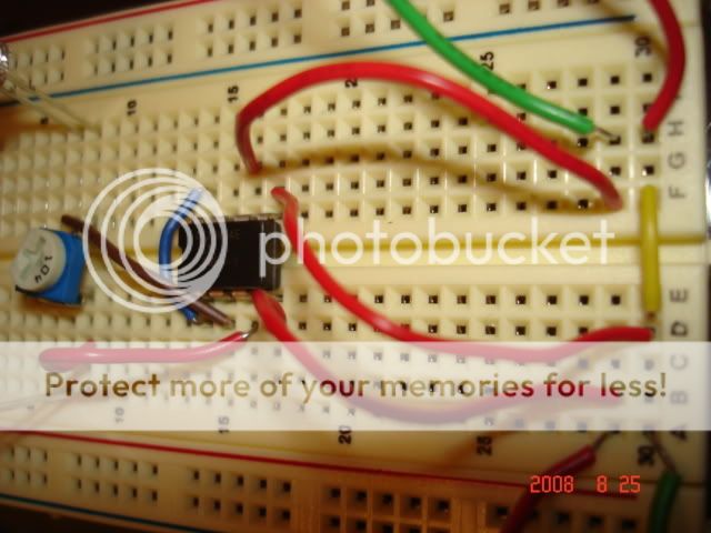
Here are a bunch of pics to what my circuit looks like:
also, I just want to make sure my phototransistors are being put in right. I have it so the emitter is on the top and the collector on the bottom. Here is a picture to clarify:
I haven’t actually build one I haven’t actually build one of those, so it is a bit hard to help you. But one thing you could do is to try and check the position of the trimpot. What happens if you turn it?
Ah! Looking at your pictures again, it seems like you mounted the trimpot wrong. If you take a look at it, it has two pins at one side and one pin at the other side. The two pins corresponds to the two pins sticking out of the side on the brown box in my drawing. The single pin corresponds to the one in the middle.
A potentiometer (is the correct name for it. A trimpot is just a small one, that you use to "trim" or adjust your circuit) of a 100K ohm has a resistance of 100Kohm between the two end-pins like a normal fixed resistor. The single pin is connected to n "arm" inside the pot. and the resistance between the endpins and the single pin is changed as you turn the pot. If you put it in the middle, the resistance should be 50Kohm between the single pin and the end pins. Turn it to one side, and the resistance between the pin and one endpin is increased, and between the pin and the other endpin it is decreased.
To make things just a bit more confusing, they come in both linear and logarithmic versions. The statement above is valid for linear pots.
Back to your circuit. The small pots are a bit difficult to fit on the board, as you probably have discovered. Just mount it as you have done in the pictures, but move it away from the other wires. It seems like row 5 and 6 are free, so put it there and use wires to connect it to the photodiodes.
Also, it seems like you Also, it seems like you forgot the link between the cathodes of the photo diodes. The single pin on the pot. should go to the cathode on both diodes. The two pins should go to one anode each and to pin 2/3 on the 386. Check the schematics again.
Oh, by the way. (This is Oh, by the way. (This is more fun than work, so I’ll just keep ranting here). What motors do you use? Are they rated for 9V? If not, you might end up burning the motors rather fast. I can see from your pictures that your 386 is an LM386N-1 which is rated for 4-12V (http://www.national.com/ds.cgi/LM/LM386.pdf). If your motors are 3V motors, you could drive them at 4V (which is the lowest voltage the 386 will work at). They will wear out faster, than if you used 3V, but not as fast as 9V.
do you thik I should leave the trimpot there or move it to 5-6 like you said?
also, i don’t really understand the cathode/anode stuff. The diagram on my phototransistor only shows a collector and emitter. (sorry im probably frustrating you haha)
Your motors are 9V, so you are safe there. They look like the 3V I use.
Look at the schematics again. From your drawing, I think that what you call 1 and 2 are the line at the end of the potentiometer symbol and 3 is the one in the middle. Follow the lines in the schematics and compare with your setup. Remember, that the horizontal lines in your drawing are connections. They are the same as wires. Follow the lines in the diagram from component to component and make sure, that you have them in the setup. Also, make sure that you don’t have any connections in your setup that aren’t in the drawing.
Pin 1 is ok. Pin 2 should be connected to the row opposite of pin 1. Pin 3 should be connected to the row it is connected to now AND the opposite row. Basically, you need to rotate the potmeter 90 degrees clockwise, but the it won’t fit on the board. That is why I think it would be easier to move it and make the connections with wires.
I think that the best thing you can do now is to print out the schematics and follow the lines. Make sure that you have the all right connections and none of the wrong.
ok so I decided to move the trimpot. Got really frustrated with trying to make it fit across the gap! haha but before I start building the circuit again I thought I would make another breadboard
You make the same mistake You make the same mistake again. You forget that the horizontal lines on the board are connections. You have connected pin 1&2 on the potmeter + the red wire connects the 3rd pin to the other two. Are they all connected on the schematics? (hint: no) Also, you have connected both pins on the photo transistors. Are both pins connected on the schematics?
I’m glad you finally got it to work. As for the two motor wires into one hole, remember that in a breadboard, each horizontal strip of holes on each side is all connected with each other. So you can just put one motor wire into one hole and another wire into another hole to the left or right of it, and that’s exactly the same thing as jamming them both into the same hole.


