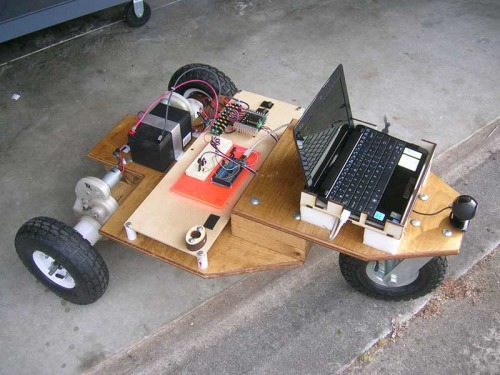
Fundamentals of a GPS guided vehicle

Coding questions

Awesome work! I currently have a project for navigating the desert and I want to use your system’s layout and code (of course, I’ll credit the work you have contributed) but I have some questions about the code. 

In the turn functions, where you are obtaining +/- 2 degree accuracy, why do you only set motors 3 and four to low? This is done in both the right and left turn functions. Are you numbering your four motors in a certain pattern on the vehicle? I copied the code below:


if(headingcompass+2>=heading){

  if(headingcompass-2<=heading){

      digitalWrite(mo3, LOW);

        digitalWrite(mo4, LOW);

    return;

  }

}

One more quick question: to make it +/- 2 degrees, shouldn’t the statements be >= and <=?


Thanks!


mo3 and mo4 are actually one

mo3 and mo4 are actually one motor just the different leads of that motor. So i am writing both leads to LOW. The way my front motor works is if you write it LOW, then it sets the front tires straight. So the code is setting the front motors straight if we are within our +/- 2 accuracy. This is basically where you put the code for making your tires turn straight. 

Now that i think about it. You are correct that that functions needs to be re written. I will get right on that. 

Your project sounds very interesting. Keep us updated on it.

Some more "stuff"

Thanks for that information. I actually went back to look at it again and figured it out after posting, sorry about that. I have two more coding questions. In the code that you provide on this page, there is no instance of the call to the distance function anywhere, but in the code that you posted, the call is in gpsdump, I am assuming that that is correct because otherwise Distance would just sit there.

Second, how does the compass data get read in? I looked through both the code here and the “complete code” and I could not find anything where the pin 4 and 5 are being read. I don’t actually know how to work with compasses, that question was just going off of the wiring for other sensors, where you have to read in from somewhere. 

Thank though, this is really great work. 

The code calls to distance

The code calls to distance in the main loop, right after it has new gps information then it goes to void distance to use that information. The compass uses i2c to communicate with it so yes it does not look like the code for like analog sensors. It uses the Wire library. 

at the beginning of the code we set up the variables for the compass:

#include <Wire.h>

int HMC6352Address = 0x42;

int slaveAddress;


and in void setup(){

  slaveAddress = HMC6352Address >> 1;     

Wire.begin();   


below reads the compass:

     Wire.beginTransmission(slaveAddress);        //the wire stuff is for the compass module

  Wire.send(“A”);              

  Wire.endTransmission();

  delay(10);                  

  Wire.requestFrom(slaveAddress, 2);       

  i = 0;

  while(Wire.available() && i < 2)

  { 

    headingData[i] = Wire.receive();

    i++;

  }

  headingValue = headingData[0]*256 + headingData[1];  

headingcompass = headingValue / 10;      // this is the heading of the compass

A different compass

In the code, the int *******slaveAddress starts with the model number of the compass. If I want to use a tilt compensated compass, as long as I connect it the same way as you connected your compass, then do I need to change anything? I don’t see why it would be needed, but just to make sure. 


Thanks a lot,

bogn120

Read the data sheet of the

Read the data sheet of the one you want and it will tell you the factory slave address. Also the datasheet will tell you how to operate it. It may turn out to be very much different from this example.

question about the compass

But if you want to use the compass in a flying or sea vehicle you need a tilt compass and then it goes more expensive.

And that is a problem in our days.(find money)

I have designed and ordered

I have designed and ordered some custom PCBs made for this purpose. Here is a link to them

Great write-up. Just what

Great write-up. Just what I’ve been looking for. I’ve got a Sabretooth 2x25 controller that looks to my Arduino like 2 servo channels , one channel left and right and the other one is forward and back. Should work fine. Right now it’s setup for a vision system.

Asus.jpg


Dave

That is a very cool vehicle

That is a very cool vehicle you have. I see you live in Florida too, where at? 

Eustis…by MT. Dora (about

Eustis…by MT. Dora (about an hour north of Orlando)

Quick question…

I’m noticing a discrepancy between what the Config tool writes to the eeprom and what the AVG program reads. The lat and log are slightly off, although when read back into the Config tool it reads correct. Have you noticed that on your setup? I’m using hardware serial (I can’t get nss to work despite using the old servo lib). Not sure if that makes a difference or not.

The error between the two readings is only a few feet, But my robot is way off the waypoints.

I’m using a LS20031 gps @ 9600 baud if that helps.

 Thanks,

 Dave


I havent doubled checked to

I havent doubled checked to see what is actually being read by the arduino, never needed to because i have been pretty accurate. I am not sure if your setup would change things. I will have to test mine and see if it is correctly writing those GPS points.

Finally working…

My problem with accuracy was due to the radius being set to 10 (meters?). I set it to 1 and it’s much better. It occasionally overshoots and has to correct, but it’s within 2-3 meters. I still don’t know why the waypoints read off the eeprom are slightly off, but I’m pretty happy. Check it out.

http://www.youtube.com/watch?v=OXAnZ_rxcM0

Thanks,

Dave

1 Like

Yes sounds like i need to

Yes sounds like i need to get your GPS’s accuracy. Looking good there, came close to that fence. Cant wait to see what you add.

I wish i had found this a couple of months ago!

I could write this now. I went down pretty much the same path (pun intended) except I have a little more granularity in turning. I have functions for turnLeft and bearLeft for example. One thing I have found is that you can get really good relative accuracy with 2 of the same GPS units and even pretty cheap ones. My favorite now is the Pharos GPS-500 that came with Streets 2008. You can get them (currently) from a seller through Amazon for under $20 delivered in the US and you can find Streets software on eBay with the unit for less than that quite often. You have to crack open the plastic case and there are TTL leads right there. I will post a picture below of the GPS-360, which has the same pinout, wired up to an FTDI. With a little Googling, that will give you the pinout I am too lazy to document.

Anyway, with the GPS-500 under an open sky, I can get an exact hit, sort of. It will immediately get within 6’ and then when sitting still it will get just enough “chatter” to mill about and will hit the exact spot I want it to.

My main purpose for this (which I can’t get too specific about due to an NDA) is a USV and affected by wind, waves and current. One thing you have to do due to those conditions is switch to getting the course from the GPS instead of the bearing from the compass. I had to use a tilt compensated compass also.

I also have a wireless link in mine so I can keep updating it. The target may move, or I may override and drop into “traditional RC” mode.

I hope to get this working on a land based toy in the next few days to work on another wrinkle. I have a remote control for it that is also an Arduino. It has a GPS and compass in addition to a joystick. That means I can tell which way I am pointing the RC box and how far away it is. Any lights coming on?

I am also working on obstacle avoidance and rerouting. That is painful. 

Hopefully one day soon the guys I am working with will get the product I mostly work on to market and I can show it off. In the mean time, I can reveal non proprietary technology. I will post my AGV toy in a few days (I hope). I only have to create the turning and driving functions for the vehicle I am getting (an ESC/Servo type, just like my main project, so it is mostly tweaking PWM values) and the brown truck is supposed to drop the toy off tomorrow.

Here is the promised picture of a GPS-360. If you get a GPS-360 or GPS-500, you crack open the plastic case and solder on the pins or just solder wires. Look up the FTDI pinout and you can tell what is what. It will spit NMEA at 4800 baud. You will like the 500 better for small robots. Both are great in motion but the 360 bounces in a wider (still small) area when still.

a tweak needed for high accuracy with some RC units

If you are going for an exact hit from very nearby, you will never get there going forward and always trying to close the gap if it is within the circle of your turning radius. This only matters if your turning radius is high, but there are a few vehicles, mostly larger faster high end RC vehicles, that don’t turn that tight. There are two ways out of this problem. One is to use reverse, if supported, and cut your wheels the opposite way to swing the nose toward the target. The radius is very small and since you are pointing out and not in, you can point at all coordinates. The other is a less efficient twist on the same logic - pointing out. When the target is nearby, go the wrong way (left when the logic in the code would normally say right). You will go more than 180 degrees around, but during the last 180 degrees, your nose will sweep across pointing at all coordinates within the circle of your turning radius had you gone the “right” way.

I hope to get a video this weekend. My truck chassis is operational (controlled by Arduino) and I just have to get a compass and GPS running in it (same ones I have working in other units; shouldn’t be too bad) and port (copy mostly) some of my nav code.

EDIT - oh yeah - my BECs (I have 2 on different ESCs) are registering over 6v; too little to power a regular VR (an LDO would work) but enough to make me nervous about going straight to 5v VCC. A diode drops the voltage a little and calms my nerves…

I’m confused

When connecting the esc to the arduino, where the instructions for using that board? is it different then conneting it to an arduino? I am still a beginer at robotics, but once I get more advanced I plan on creating an agv because I have a fast rc car that has a esc. 

thanks

-Mark

You just have to connect the

You just have to connect the ESC signal pin to a PWM pin, which in this case there are only 2 left ( pin 9 and 10). Also make sure to connect your grounds. 

some questions

I didn’t understand a few thigs:

  • how i select waypoints?
  • the codes that you had published fully work?