Attiny-Duino or whatever?

@Max: Yes, i did programm my

@Max: Yes, i did programm my Tiny’s with help of this page.

@OddBot: Yes i know, but I want to build my own one :wink: Also want to use it as a educational board for our workshops.

@mogul: Yes i know that too. We had already trouble to fit the program into that tiny memory. But on the other hand, it’s only for projects which does not require more than the Tiny can offer. I don’t want to build a 4-leg walker with that. For programming purpose, we are going to include a standard 6-pin ISP header.

Here is the 6-pin header already included, buit the µC is an Attiny2313, not the 85 

Soon I will modify my insect bot with this new board to lower the costs for the workshop and make the build even more easy.

The insect bot is running with 2 servos and one ultrasound sensor and just a coulpe of lines code, good to use the Tiny.

Re: updated post with board

I was about to be upset that you could get your board built inside of 27mm ^2, then I noticed that you didn’t have a vreg on board and I was happier. :stuck_out_tongue: I would have suggested looking at https://www.robotshop.com/letsmakerobots/node/32665 my board, but, the PIC and AVR are just too different to be able to make them interchangeable.

How was this updated on June 8?

You’re not that far of the US time zones. If time travel, please include instructions!

By the way, is there documentation anywhere as to which programming functions are supported by the ATTiny and which are not?

Oh, there’s enough room to

Oh, there’s enough room to squize in a TO92 v-reg (about 250mA) on Lumi’s board. As for yours, you can make it smaller if you use a 2 layer board. It all depends on your needs. Of course, if you use SMD, you can make it smaller than a quarter. But anyway, both boards look nice, congrats both of you!

Thanks for the compliment!

I was shooting for single layer for my first foray into toner transfer. I didn’t want to make my life too hard to start with. :slight_smile:

Looking at your layout,

is there a concern of the voltage drop across the LED?

I couldn’t stand it.

I had to try to do better than 27x27. :slight_smile:


I managed 22.9 x 24.4 with a straight ISP header. That 6 pin header plays hell with making a single sided board.

This is what I managed with 1 jumper. It is the same size as above.

 
I am concerned about the continuity of the ground plane though. 

There is still room for more

There is still room for more components and as I said, the board is far from finished yet. The voltage drop on the LED was not considered, just the space the LED will occupy :wink:

Haha, i am quite far from

Haha, i am quite far from any time zone, especially US :wink: I am in UTC/GMT +8 hours. So at 0:38am was already June 8.

The Attiny will support at least the servo library and the main functions:

  • pinMode()
  • digitalWrite()
  • digitalRead()
  • analogRead()
  • analogWrite()
  • shiftOut()
  • pulseIn()
  • millis()
  • micros()
  • delay()
  • delayMicroseconds()

Great little board birdmun.

Great little board birdmun. well, that’s hard to beat :slight_smile:

I will improve my board later, right now I am bound to the soccer bot. What software are you using for your PCB design?

I am struggling through

gEDA. It is one of the common Free Open Source Software EDA packages available for linux.

Last time I promise. :slight_smile:

I took one last stab at getting a single sided board with the standard ISP socket. I won. :slight_smile: 24.6 x 24.4

The little black blobs all over are some of the labels. I couldn't manage to delete them, so, I shrank them as much as I could.

Well, that’s cool. I will

Well, that’s cool. I will try to improve mine too and shrink it to the minimum. Will see how small i can get it.


I know I said final. :stuck_out_tongue:

Laying out PCBs is like putting a puzzle together.

I got it down to 24.4 x 21.6 :)

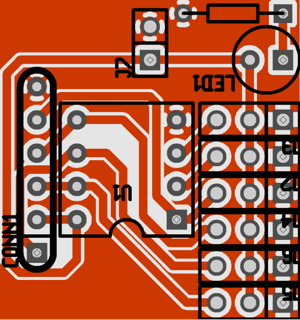
Looking at it I could have rotated the resistor around so the ground would be in line with the grounds on the 3 pin headers. Slide the LED back towards the resistor. Rotate the 2 pin power header CW and move it back toward the LED. You might have enough room for a vreg and a capacitor. If you stand the resistor up, you might be able to get the LED back inline with the power rail of the 3 pin headers.

Haha, it’s never final :slight_smile:

Haha, it’s never final :slight_smile: But i think this one is hard to beat. I do not have much time right now but I also will improve my Attiny PCB. I hope to get it smaller than it’s now by separating and relocating the I/O header pins. They do not have to be in one big block right :wink:

I noticed something on your newest design that caught me too.

Your current limiting resistor should be between either the power and anode or ground and cathode, not, in parallel with the LED. It won’t affect board size only circuit layout.

Damn, i knew that something

Damn, i knew that something looks wierd…thanks :slight_smile: Will change it right now.


Errors in the schematic:1.

Errors in the schematic:

1. Pin 4 (GND) of the microcontroller should be connected directly to pin 2 of the Power connector (GND).

2. Pin 1 of the LED (anode) should be disconnected from pin 4 and connected directly to pin 8 of the microcontroller (Vcc).

I did not check your ISP connector, so I asume it is good.

Cheers!

Kewl update

Seeing a video will be very nice. :slight_smile:

Tonight bird, tonight :slight_smile:

Tonight bird, tonight :slight_smile: