Well, not really. If you are talking to these open servo things with I2C you must already have a way to assign a unique address for each servo, right? So if the micro in the servo can read a standard servo signal (for when it is not being used in the I2C configuration, i.e. as just a servo) it could just as easily be programmed to decode “its” signal from the composite frame using that I2C address to determine which of the 9 channels in the frame belonged to it.
This is all just hypothetical of course… you would be limited to only 9 channels per “chain”, using the standard FM r/c radio composite frame. I don’t really know why you would want to apply this when you already have a purely digital bus available, other than it would be a single wire type of protocol. If you wanted to get really crazy with it though you could code a small CPLD (big PAL, non-volatile fore runner to an FPGA) that you could “write” a PWM value to 1 of 9 “registers” from your host micro and the CPLD would encode and transmit the composite frame. This would offload the host micro of the timing critical chore of building the frame and transmitting it. Lattice has several small 4000 series parts that would do this easily (and I’m sure xilinx would have parts capable of doing it too.)
ok, I think we just confused multiple topics… I was replying that you couldn’t bus standard, unmodified servos. I thought you were addressing that same topic…
uh, ok, yeah you are right you would need something in front of the standard servo to set an address and decode the frame. Sorry. I went on the tangent of a modification of the open servo design to include the decoding so you could effect a simplistic single wire daisy chain of several of them (despite my earlier power distribution concerns of course.)
quick update:
Back up and running on a new Gumstix. Now using the unreasonably uncommon screws that hold the things together. The Robostix expansion board is working as expected, I can flash it with the Gumstix via uISP. The I2C bus is up and running, level shifted to 5V via the Robostix board. Communication to a couple of OpenServos has been a success via the /dev/i2c-x interface.
Did some quick and dirty proof of concept bridging between the servos and a remote socket connection. Went smoothly.
TTL serial to USB adapter running off the console port on the robostix as well (I was originally using a tweener). I’m sure this will come in handy for when the wifi card decides to not find the network, I’ll be able to just plug a laptop into the side of the bot and watch/help it boot.
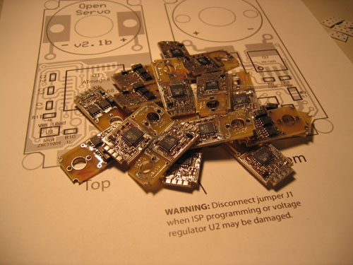
Gaining some confidence in the latest OpenServo hardware revision, about ready to order enough boards to be fabricated to build 18, already have the components.
I’ve placed a brazillion orders for all this necessary bits to do home PCB etching for building the power board. Most everything has arrived except the most important bit (the chemicals) for which I failed to hit the final really-commit-the-order-I-actually-want-you-to-send-it-to-me button, setting me back a week or so. At least they still had my order in the shopping cart when I returned
Worked out the design for a tiny little board that will rest on each leg driving only a momentary button and 3 colored LEDs for debugging purposes. I had found that even though I made a spiffy rendering of the bot on the PC interface, it was tough to watch the feedback displayed on the screen and to see what it’s reacting to in the real world simultaneously. Simple things like knowing whether or not the ground contact sensor engaged while its running some of the posturing code was difficult. So in comes little UIs on the actual bot that will be used to indicate whatever is of interest at that moment in development and to allow some simple interaction with the code via the buttons to do things like shut legs down or change the modes in which they are operating. My first stab at is awfully damn small but single sided. Hopefully it won’t be too ambitious for my first etch.
Heh, I’ve had experience with those “really-commit-the-order-I-actually-want-you-to-send-it-to-me” buttons before.
You’d think that you were launching a hellfire drone, what with all the double-checking some sites do.
Next thing, you’ll need to turn two keys sycnronously.
Anyhow, your whole project revamp sounds really neat.
I’m interested in hearing how good the position/strain feedback from those new Open Servos are.
Since I’d have to pay for an entire new set of servos, when HiTec starts selling the new ones, to get that from my current ones, I’m thinking about jumping onboard.
Those LED’s sound neat, too.
I was thinking about doing adding LED’s to my bot just for fun, but no one makes black ones.
The larger motor Open Servos would be amazing, especially if Jim makes SES brackets just for them.
That just opens up so many possibilities.
Perhaps a child-sized biped…
or a normal-sized biped with gobs of power…
The only problem would be powering the beast without weighing it down too much.
Hobby servos draw enough current as it is.
Perhaps LiPos would be necessary.
Niccceeeee - Hey Andy, did you etch all of those yourself? If so, what kit? I’ve never etched before and after reading about the OpenServo project I considered giving it a go. Any suggestions would greatly helpful. Thanks
No they are ExpressPCB. I’ve just gotten setup to do some home etching but haven’t yet tried it. I think my first couple attempts are going to be simpler boards, single sided, no vias. The current OpenServo layout is a tough one by account of the home etchers. Vias under the chip and a few features that are particularly rough for doing at home, but “ginge” (Barry) over at the OpenServo forums has many such successes.
So you used to ExpressPCB huh? So who actually etched and cut the boards then? vendor ? In either case - lots of work in making 18 - well done and thanks for the reply
ExpressPCB etched them. They have a service called something like “quickboard” which gives you 3 copies of a small panel for something like $60. I had a layout that sqeezed 6 OS boards per panel. Once they arrived (etched and in 3 panels) I cut them up and assembled the components.