I have built my first robot, everything works fine EXCEPT one thing: the ranging sensor. When I try the simple readadc 0,b0 / debug program, the value is nearly always 158-159 ocasionnaly flashing to another value. Any help with this?
Many thanks.
PS: I am using the Picaxe Programming Editor and a Sharp GP2Y0A02YK0F
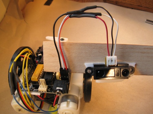
https://www.robotshop.com/letsmakerobots/node/75 your picaxe board has the pins arranged from outside in, in order of power, signal/sense, ground. You have it connected as sense, power, ground. You seem to be feeding power to your sensor through the sense line. It looks like your wires are connected to your sensor correctly. I am not sure your sensor is still functional though. You will need to swap your wires and try again.
Thanks for the proposition, unfortunately it did not work and in fact the robot smells funny now… PS: this might be because I did not fully understand what you ment by outside in, were you talking about the servo cable or another? I switched the servo cable. The power cable must be working fine since the motors are functionnal…
Yup, the ol’ 28x-board switch-a-roo got you. For some reason, picaxe decided to put the “data pin” in the middle, with the power and ground to each side. I have no idea why they did this, but it has gotten a lot of us. I lost 4 sharps all at once due to this problem.
Most likely, you have fried your sharp, I’m afraid. You should wire it properly (Jax got it in the comment above) and recheck your sensor. First, check it with a digital camera to see if one of its “eyes” is glowing. If neither is, your sensor is dead. Assuming you are getting a glow, do your ADC read and a debug to see if your values change as you wave your hand in front.
Wish I had better news for you, but you are with friends in terms of getting bitten by this one.
Many thanks for your help. However I must say that is very odd: I received the cable as is and even if I change it around I still won’t get the right combination… Does that mean I should cut the wires in the middle and reconnect them the right way?
Thanks for the tip. At least now I know! I have been trying to work this out for hours. Would you happen to know if the Picaxe compatible wire for sharp, with no tampering required, is available on the market? It seems really odd that no manufacturer would simply ignore this problem…
That being said, the page here that shows how to build it specifically, via a picture* (right after the mention of the programming software and the first time you program your new creation), point out that the wiring is different between the sensor and the PICAXE board.
***PICTURE:
If you have indeed blown your Sharp, you can buy a PING))) from a local retailer that sells Parallax parts (more expensive than buying a new Sharp). Concoct a sensor from a 38khz IR receiver, and, an IR LED, pulsed at the proper frequency (cheaper, but, more difficult). Buy an SRF05 or SRF04 from eBay for $3 to $5, and wait for weeks while it ship (least expensive, longest wait). Buy a new Sharp, and wait for it to ship (least new things to learn to make it work, shipping will be quicker than the SRF04/05).
The next thing you need to pay attention to is, if you buy a new Sharp, make sure it is analog, if you want to use it like the one you are replacing. Otherwise, it will be digital and will be read differently. The other options I mentioned above are all digital except for the Sharp, if you buy it as an analog version.
The plastic “tongues” that hold the wires in place on the black connnector can be lifted carefully, and, the wires will slide out. Once you get the red and yellow wire out, just push them back in to the spots you need them to be in.
It worked. Thank you very much. Seems the sensor is not fried after all. However, although it can easily read “readadc 0, b0” it constantly displays the same number for “readadc 1, b1” and “readadc 2, b1”. Any help with this?
readadc 0, b0 reads on analog pin 0 and stores the answer in byte 0. You probably don’t have anything connected to the other pins, so, there won’t be a useful response.