Okay! I have tried as hard as I can to follow along, but you guys with your “bits of fun” are giving me a serious headache now.
This forum really needs a **Genius Free Zone **so guys like me can still come out to play safely.
If you fellows don’t mind indulging me, please let me restate and summarize what I think is happening, and anyone please tell me where I’m right and explain to me where I’m wrong. Bear in mind that I don’t know the full capabilities/purposes of all the goodies that Lynxmotion and BasicMicro provide:
The Master provides control signals to position the Slave in a manner somewhat analogous to the way an indoor control rotor used to control an outdoor TV antenna rotator. (Little history lesson there for you young guys. )
There are many ways matched motor-like combinations can control each other: stepper motors, motor-dynamo, etc. In this case, continuous rotation is ruled out, and reversability is required. So the matched combinations are pairs of servomotors in which one of the servos is modified to act like a potentiometer. This pot servo is in the master.
The pot servo modifies an output voltage which becomes the input signal that tells the servo in the slave what to do.
Here’s where I start getting shakey, so watch me carefully.
The master and the slave can have completely separate power supplies of differing voltages. So to avoid power conflicts, the signal wire between them should probably be isolated somehow, perhaps through an optoisolator.
And now I am completely lost.
How does the signal wire connect? Can it go directly to the signal pin on the slave servo? Or can it go to an input pin on an SSC-32? Or must it go first to an input pin on a BotBoard II before going to the servo or to an SSC-32?
Where does isolation occur? Do the BBII and/or SSC-32 provide it, or must there be an additional component?
Thanks to all who help. And remember, the fact that some of us don’t understand all this immediately does not diminish the lustre of those of you who do.
I don’t want to be a spoilsports, the project looks very interesting, but did you really need to use 6 hitec servos (cheap ones, but still) to get potentiometers ?
This seems to be incredibly wasteful, considering that big potentiometers with enough drag to stay in place by themselves cost less than 50c a piece…
Anyway, I see that you are going for an interesting non-IK route, I’m looking forward to see it move with it’s puppet mounted on it
However consider: Same mechanical connections, duplicate master/slave hardware. Better pot (perhaps) then in a really cheap R/C servo). Range and scale of pot would be the same as in the slave servo. (oh yeah, they’re both linear pots, so they HAVE to be equal).
Simple interface to the required BB II. Which answers the previous question, we typically don’t need the isolation with the master and slave in proximity, we’re using TTL levels into (OK analog 0-5 V) and out of the BB II. Six axis, not enough inputs just on an SSC-32, and you’d need a uP (BB II) anyway.
Never used motor-generators to transmit position, maybe you mean Selsyns or Synchros?
Xevel:, yes you are totally right and it just seem a bit of a waste. its a shame to mod the servos but i do keep the boards so if i need them at a later date i can “fix them.”
and trust me, if my programming skill’s weren’t as bad as they are, then right now we would have a fully operational Stewart Platform working with Full Inverse Kinematics.
Ted:
Love your sense of thought.
When i first joined, i knew nothing of robotics, except that i wanted to make one. Robots are cool!
There is still lots for all of us to learn, and the good thing is, is that we can do it at our own pace.
I certainly need to learn more. From what you see here on these pages, and other posts iv made 'i have only learned these things through everyone else, and i have them to thank.
It empowers me to think i can inspire others or even teach others, but its great to see projects grow from nothing.
Create, Innovate, … Inspire!
Alan:
i did think about putting one on the top but id have no use for it. after all, iv already been greedy with a 6AxisJ/Stick anyway.
Well, I might be able to help with the mathematical side of the IK computations, and make code to demonstrate it if you are interested.
With the rotating actuators, it’s a little bit more complicated than a standard Stewart platform, but I scribbled some stuff on a piece of paper and I think I have found how to do it
Only thing I can’t do is write it in Basic, but I can write it in a way that makes transcription to Basic code straightforward.
cool, well that very kind to offer your help. i think i stick to the telemetry for this project, but i would be very interested in getting the “platform” work with IK for future projects.
would be a very interesting piece of code to look at.
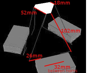
not really. precision is not key. you will notice that the two top platforms are different sizes. to get them working a little better i could make them the same, but its not important.
i could also get the servos in the slave to have more movement in it than in putted from the master. like 2:1. small movement on the master will result in larger movements in the slave. ??
Thats awesome!
You always come up with some cool stuff!
I wonder if FK is hard to do for a Stewart platform?
Is it hard to operate the 6DOF joystick? I mean, it looks like the joystick should be fixed to the table. Does shorting the motors give to much friction, maybe a resistor to lower the friction?
apparently the FK is quite a challenge. IK can be solved quite quickly by this is all iv been told.
There you go… there’s a challenge for ya.
There is not too much friction and its quite easy to use. i haven’t soldered the motor wires together otherwise i think there would be too much friction.
your right i do need to attach it to a more stable surface.


 )
) )
)